Garage Unit Doors, Table and Shelves
I head into the final stretch with this one and I am honestly quite relieved. Some projects just get a bit long, maybe it’s because in our small workshop it becomes hard to move around a large item and it always seems to get in the way of everything else, both in time and space as well as other projects I may be itching to get to.
As always it isn’t “all down hill from here” so to speak and deciding on the hinges for the doors brought on some hard thinking and research which caused a bump in the down hill section of this build.
I often use the horizontal braces at the bottom of my workbench to store wood that I am using on a project and this time was not different with the remaining four sections of raw pine waiting to be processed. At just over 2 meters long they were sticking out on the sides just far enough that I was unable to move my bench to its usual position in the workshop and it was a relief to get the lumber out from under the bench and processed.
And that is where we’ll start, with a detailed description of how to get the lumber out from under the bench.
Step 1 - Move planks:
Start by moving one’s self to the side of the bench that will allow the most room to manoeuvre when sliding the planks out. Now bend your knees and grab one or more planks before starting to pull towards you, do avoid those splinters. While pulling the lumber towards you move your hands along the edge until you reach the middle, grab on to the sides and start moving yourself backwards until you have fully extracted the plank from under the bench. Now stand up straight and place the end of the wood on the edge of the workbench and walk forwards up to the point where the wood is fully supported by the bench top, now push the full length of the plank onto the bench making sure the wood is centered on the bench. Repeat this process until all lumber has been moved from under to the top of the bench. Remember to bend your knees and avoid those splinters.
I wonder how many sentences you were into Step 1 before realising I was having some fun with you?
On to step 2.
Step 2 - Prep raw lumber:
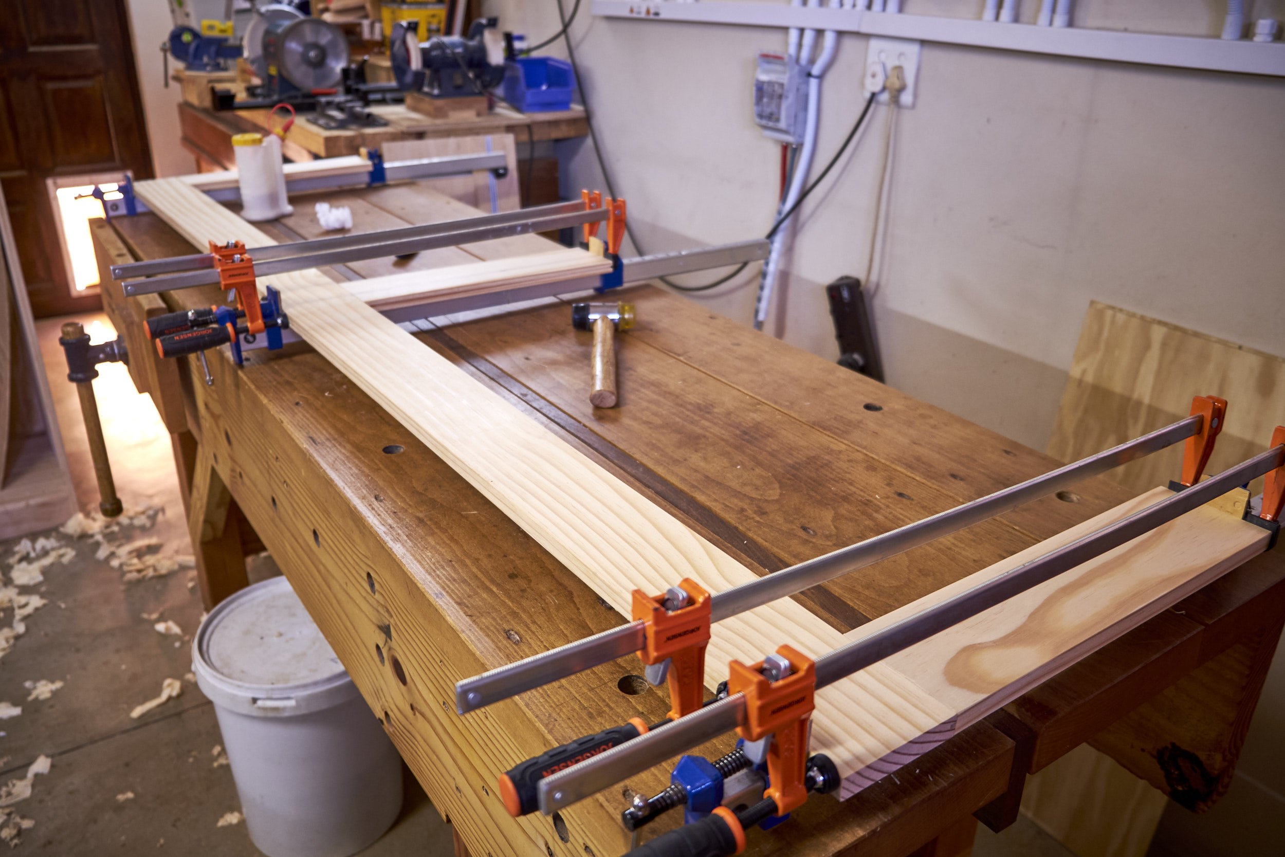
Nothing new here apart from the fact that I wanted 100 mm wide planks for the rails and stiles of the doors, for the panels that would house the adjustable shelving I wanted the processed planks to be as wide as possible - more on that later - so I needed two sections at as close to 200mm as I could.
Rather than process stock for each upcoming step as required I went ahead and processed all remaining lumber keeping the above requirements in mind and it was off to the jointer, then the planer and then back to the jointer. You get the idea, you’ve seen me do this before.
Step 3 - Doors:
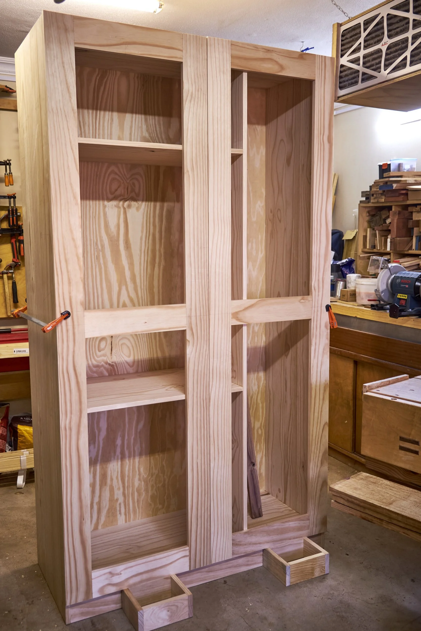
The customer wanted each door to cover half of the total width and I obliged by measuring each door based on half of the total width of the cupboard and calculating the length of the rails and stiles from there.
With all stock cut to length and final width I brought the components for each door together on the workbench and lay out the joinery for the Dominos. The DF 500 was again used to cut the slots and once the tenons were installed the frames of the doors were dry fitted to check that it all went together as expected.
Being intensely curious I needed to check if I had measured it all correctly and I offered the open frames up to the carcass to confirm if it all made “sense”. It looked good and I moved on to the next step.
Before I did though, I measured the size of the holes between the rails and stiles and as with the back panels I added 10mm to the measured values to allow the edges of the recessed door panels to be seated into the slots that were to be cut in the frame later.
Step 4 - Cut panels and slots:
Another thing that kept getting in my way in the shop was the second sheet of 4 mm plywood I purchased for the project and I was finally able to apply the circular saw and track to remedy this situation and I shortly had four door panels waiting to go into their respective holes.
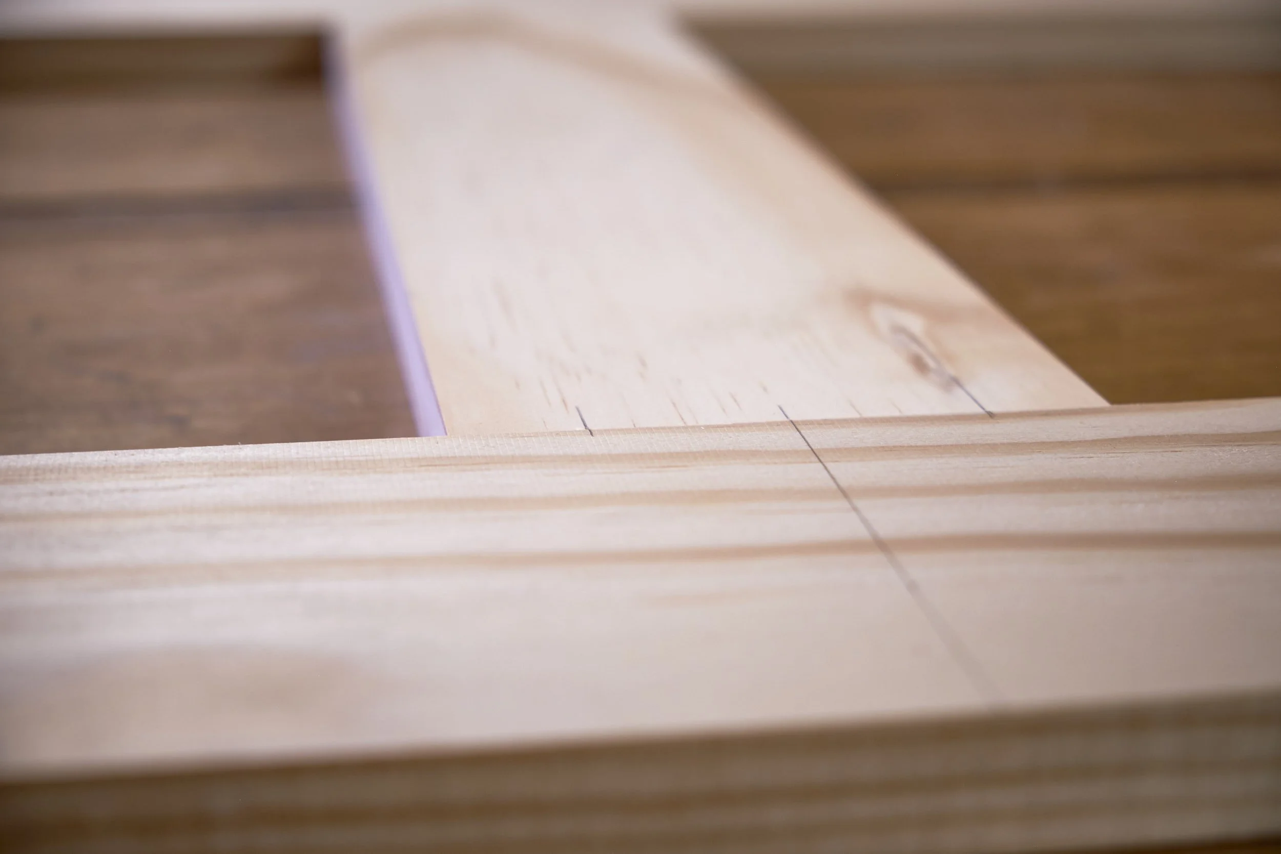
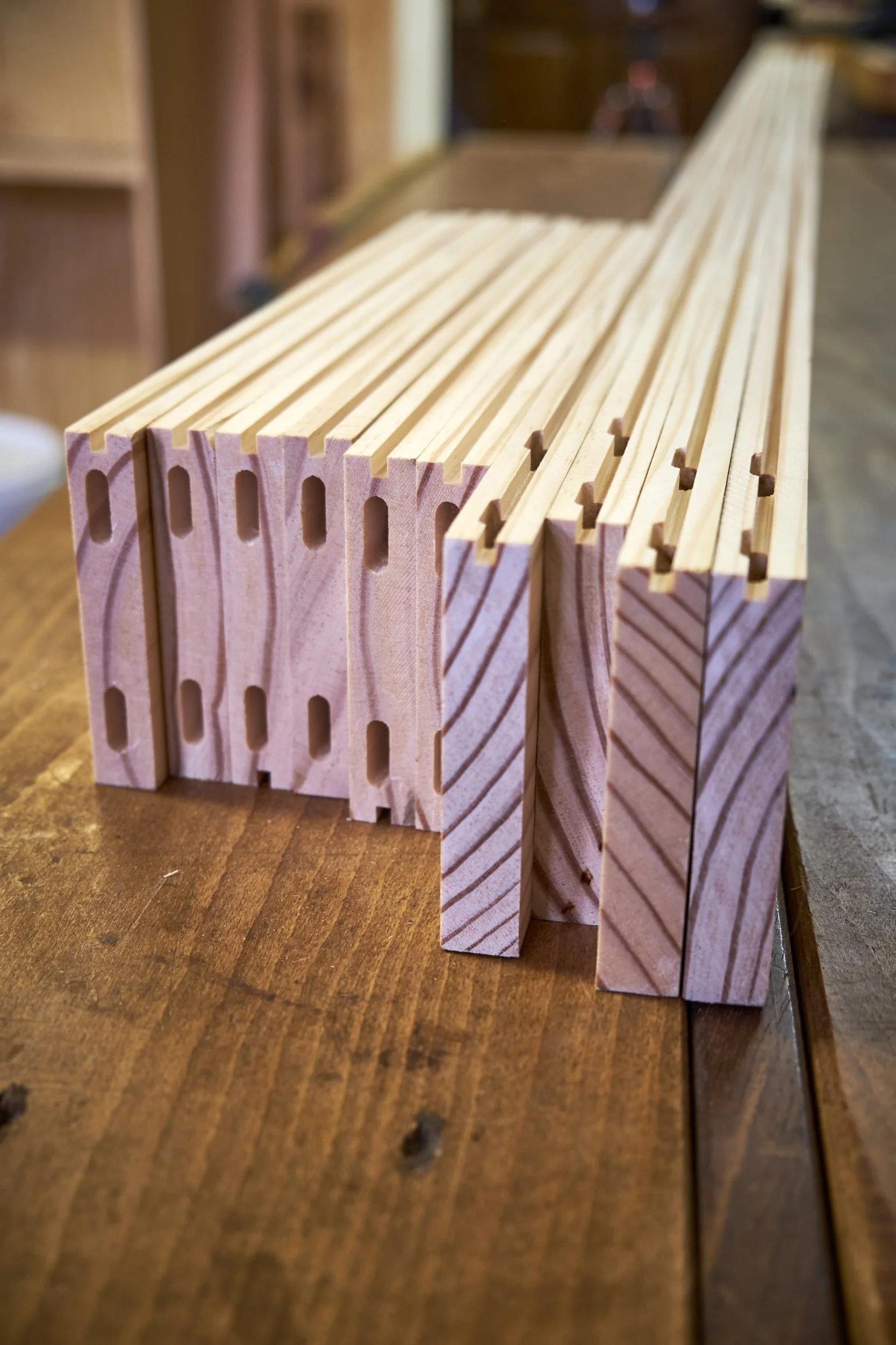
I turned my attention to the slots along each edge of the door frame and these were cut to a depth of 5mm in what I roughly eyeballed to be the middle of the frame sections. As before, marking of workpieces became important to make sure that the slots were cut on the “inside” edge of each rail and stile, with slots cut on both edges of each of the two middle rails.
The fence was bumped over by 1mm and each slot widened slightly to accept the 4 mm panel.
All cuts were first made on a test piece to ensure that the setup worked ok.
Pro Tip: Make sure that you know which face of the door frame pieces are registered against the fence during the cut. It doesn’t matter so much that the slot may not be exactly in the middle of the stock edge as does the offset from the face registered against the fence, this needs to be the same on all frame components otherwise you will build twist into the frame.
I marked the Domino joinery from the front face of the rails and stiles and then made sure to keep the marked face against the table saw fence during the cut.
Another less used tool in my workshop got some love during this step and that was my MilesCraft feather boards. Pushing a board on its edge over a table saw blade while trying to keep one face against a fence to make sure the cut stays parallel to that edge carries some risk to one’s digits and having a feather board for support is crucial.
I don’t think I have ever used these on any project before now and having bought them for a specific job I can’t for the life of me not remember what it was.
What’s nice about the MilesCraft feather boards is that they can be doubled up and used to support a wider board and I used them in exactly this manner, one on top of the other.
Pro Tip: Do not, install a feather board on the out feed side behind the blade! The job of a feather board is to push a workpiece into the fence and if this is done after a cut the feather board will push the waste back into the workpiece. It will pinch the blade between the waste and workpiece and it will spoil your day!!
Step 5 - Commit glue:
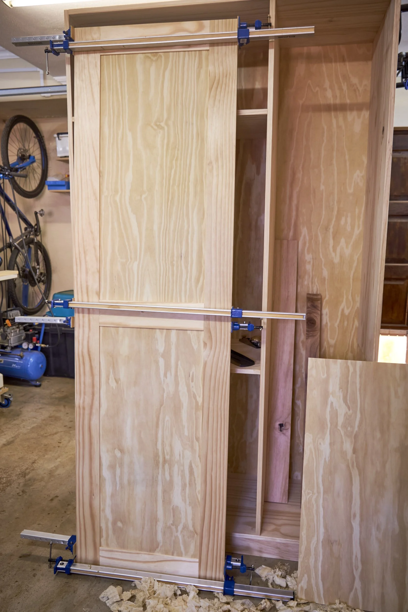
But first another dry fit and if happy I could either proceed to sand or hand plane the frame to a finish. It’s really hard to do this once the door is assembled so I did it before assembly and this time around I used my #4 Stanley on the face and back of the frame and my jointer on the edge to make sure I keep the edges straight during this step. Each plywood door panel got a quick sand just to get rid of some dirt marks I managed to get on them.
I glued the three rails for each door to one of the stiles first, making sure the components went together square and flat before installing the ply panels, lastly gluing in the final stile to complete the frame and thus the door.
Step 6 - Hinges and hardware:
Sometimes I tend to overthink things and not being particularly fond of installing hinges and hanging doors on to them, my mind turned to solutions for doing so with the least amount of effort and highest amount of foolproofness I could muster. Hidden or cup hinges quickly became the forerunner to accommodate both requirements and with the availability of commercial jigs to make installation easy it was almost a done deal.
However, considering that the cost of one of these jigs would more than cover the cost of raw materials to replace BOTH doors should I get something horribly wrong, along with the fact that I very rarely need to install these kinds of hinges in my kind of work if ever, I would be hard pressed to ever need a cup hinge jig ever again so needed an alternative.
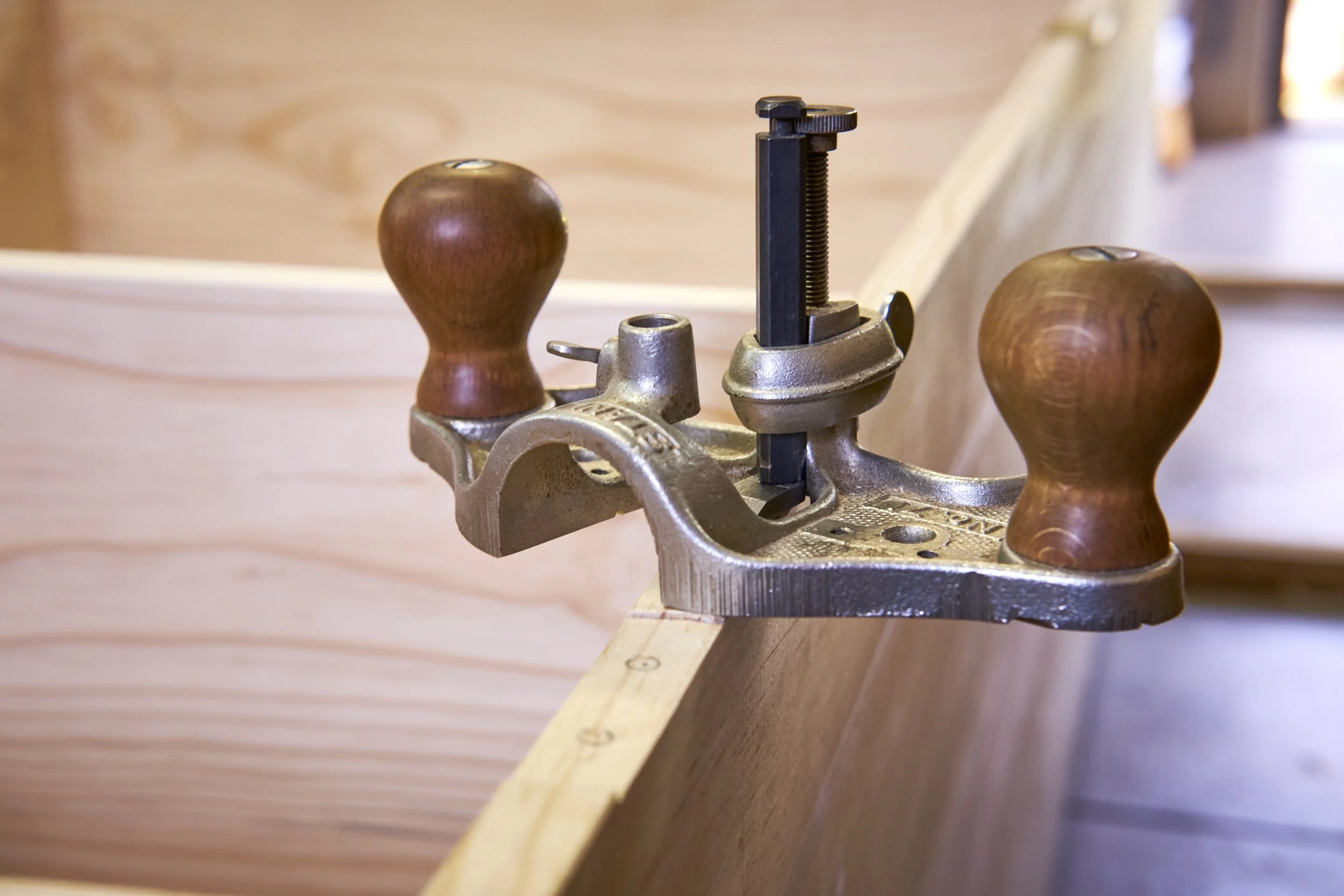
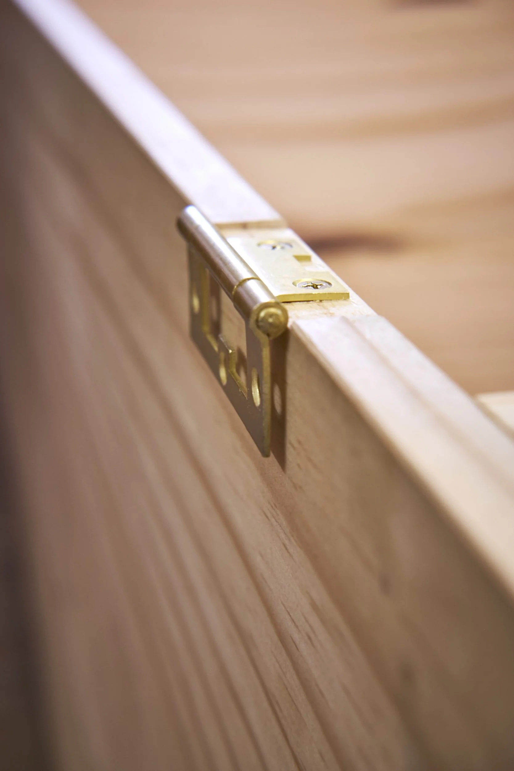
Finally I decided to use flush hinges instead, using these not only allowed me to spend quality time with my router plane which I LOVE but they were also a significantly cheaper option.
You would swear from reading this that it was my first time ever installing hinges but alas its not the case and I just don’t like installing them with drawer slides being the one thing I like installing less.
Japanese saw, marking gauge and router plane in hand I cut three rebates on each side of the carcass and screwed the brass hinges in place. At this point the carcass was flat on its back and kept off the workshop floor by my trusty MilesCraft TriGrips. To install the doors to the hinges I rolled the carcass onto its left side and put the left door down flat next to it and with the carcass slightly elevated above the level of the door I was able to gingerly butt the door edge against the hinges and mark the positions for each hinge to the door stiles. I drilled and fixed a single screw on each hinge and tested the door closure whilst having the carcass on its side and happy with the fit I drilled the remaining holes to affix the remaining screws on all the hinges.
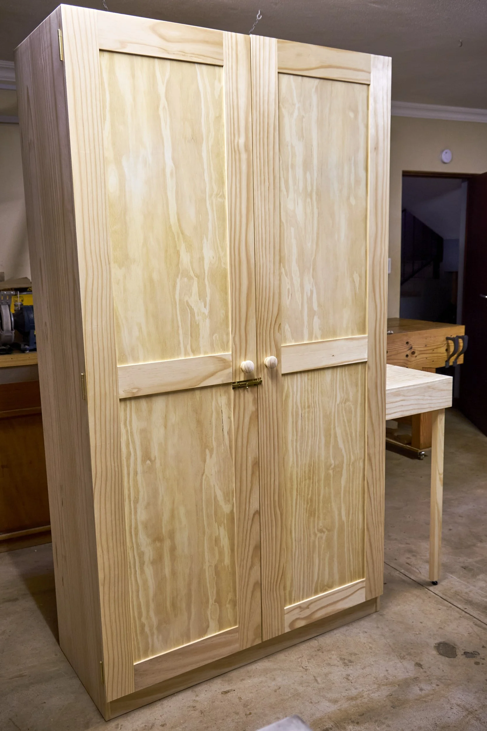
Once the left door was completely installed I used a long clamp to keep it closed and muscled the cupboard onto its feet and rechecked the door closure before clamping the door shut again and proceeded to lie the carcass onto its other side on top of the TriGrips. I installed the right door using the same steps and then got the cupboard standing upright again before checking the door open/closure and final alignment to the carcass. QA checks complete I fitted the hardware inside the case to keep the right door closed and a brass sliding bolt to keep both shut.
Things hardly ever go to plan in our workshop and the sliding bolt was no different, I initially installed it backwards but I soon had it screwed in the right way around.
I found some pine turned knobs at a local hardware outlet and these rounded off the doors perfectly.
Step 7 - Integrated Table:
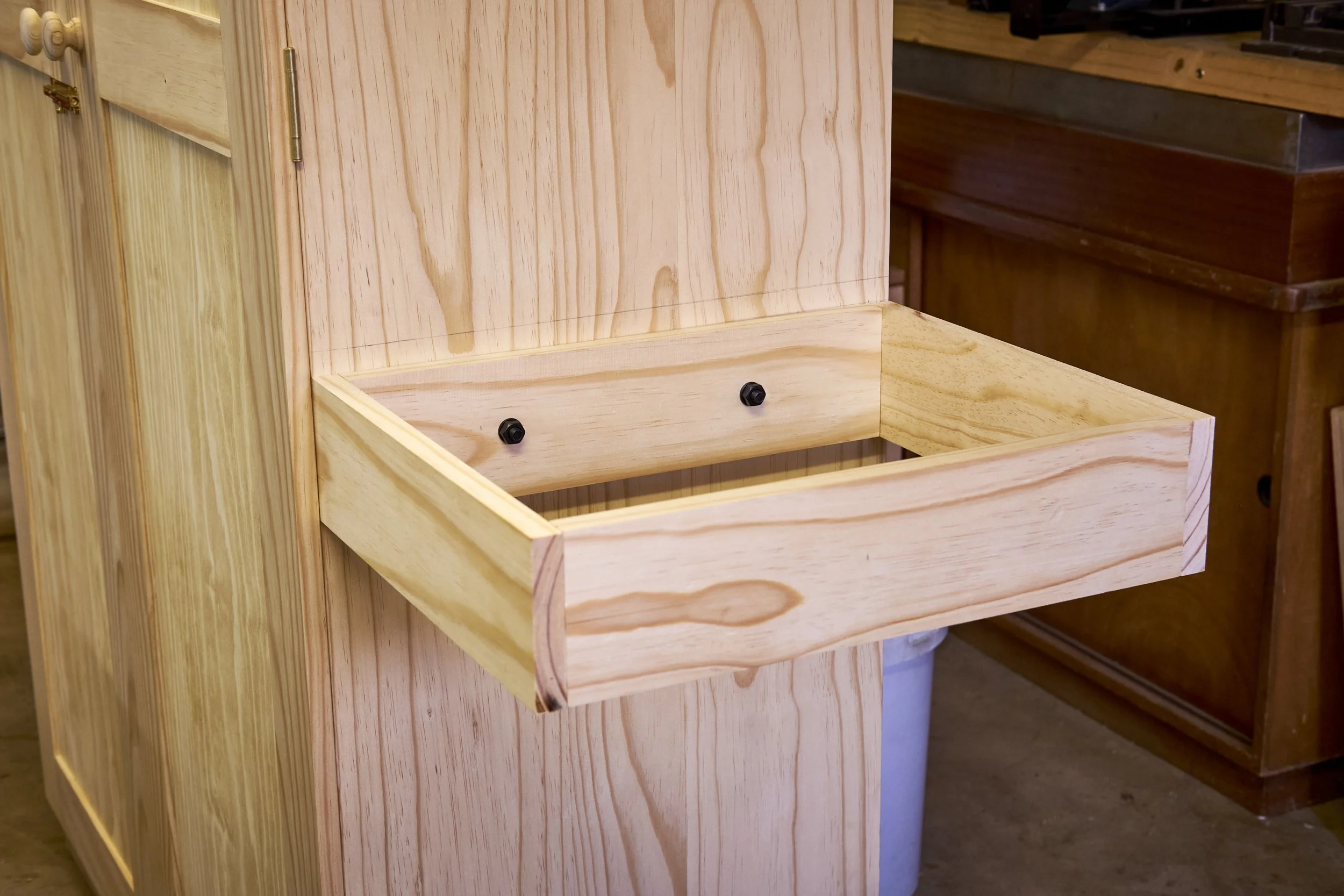
The table was relatively simple and I started by clamping and bolting one apron to the right side of the cupboard, making sure that the bolt head wouldn’t interfere with the positions of the rails on the inside.
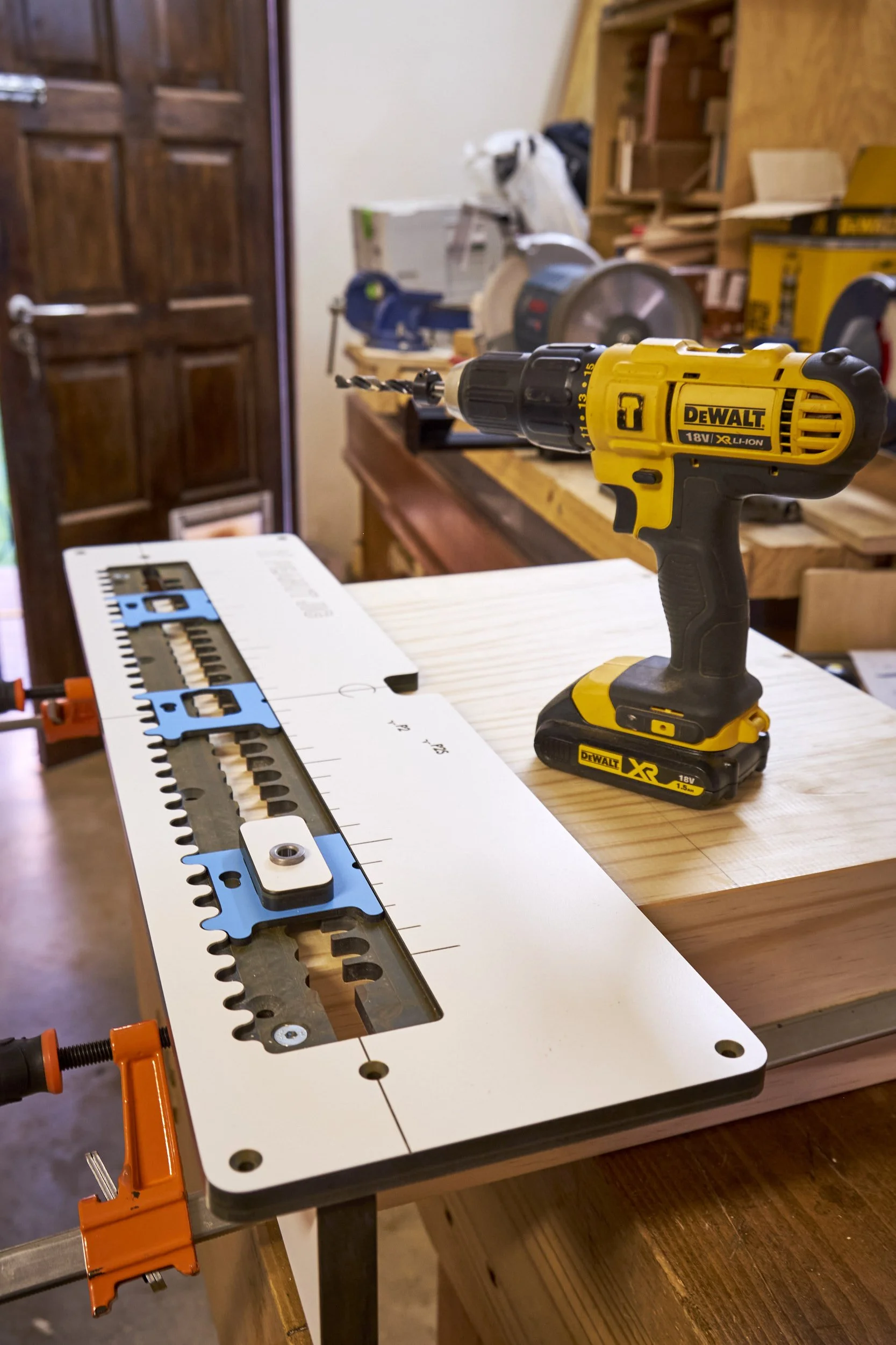
Next I glued up the apron using more dominos - my 6 x 40’s were running out fast - as well as laminated what would become the table top. With each part assembled I used 8 mm dowels to secure the top to the apron and here I used the Peanut Jig to easily align all the holes from a single centre mark. With all parts together I used my #4 smoother to finish the surface of the top and apron before bolting the table back onto the side.
With the table attached to the side and level I marked out for the two legs and cut the leg sections to length, keeping them shorter that final height so that I could add adjustable feet to each one that would allow the customer to level the table after installation (floors in South African garages are notoriously not level).
The table was taken off the side and the legs were glued in and the foot hardware installed. The connection between the legs and the apron was strengthened using dowels and the complete table was promptly installed back onto the side of the cupboard.

Step 8 - Adjustable shelf railings:
Not exactly sure what to call these but they will be called “railings” for now.
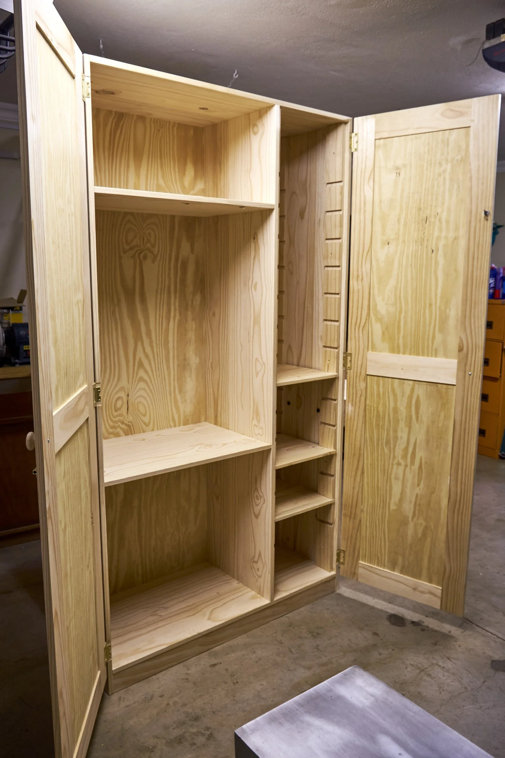
During stock prep I mentioned that I needed two planks that were 200 mm wide each and although this dimension wasn’t absolutely critical they did need to be as wide as I could manage. The reason for this was that I wanted to cut the slots that would carry the shelves from a wide plank that I would then rip in half to form a single set on either the left or right side of the cupboard recess.
Pro Tip: We are back to ganging workpieces up to make combined cuts in the name of accuracy. Cutting only two wider planks and ripping each in half allows minor mistakes in measurement and table saw accuracy to be limited to only two cuts rather than possibly compounding errors by four when cutting each rail individually.
The layout for each slot was measured from the customer’s requirement that there should be
100 mm increments between the top and bottom of each shelf if installed into adjacent slots. I took this measurement from a baseline on each plank that would represent the bottom surface of the lowest shelf position and struck a line across each rail section at the required interval making sure that the lines match up as perfectly across both.
With the lines marked I set up my Ridge Carbide dado set to leave a little breathing space for the final shelf thickness and proceeded to cut the slots into each individual rail section using the mitre gauge on the table saw. Each board was then ripped in half and fitted temporarily into the cupboard.
Next I checked alignment between the slots using some small spirit levels both between the front and back rails on the same side as well as across the space left to right and front to back. It all looked nominal and I installed the rails using screws spaced along the length of each rail section.
Step 9 - Shelves:
As luck would have it these last components quickly depleted our remaining stock for this project and some careful planning was required to squeeze the very last laminations from the leftovers and I just managed to get 3 shelves together.
As a test on one shelf I used the now most unpopular jig in our workshop, the infamous Peanut Jig as a doweling jig and was again left disappointed with the alignment of the laminations, so much so that I switched to the Festool Domino to cut slots through the dowel holes for dominos to aid with the alignment of the lamination sections.
After the glue up the shelves were kept in the clamps for a few hours and once dry my jointer made quick work of flattening each shelf and my Stanley #4 took care of the smoothing before each was installed into their respective slots on the rails to make sure it all went together as planned, which they did!
Step 10 - Delivery:
I sent pictures and a video to my customer as proof that their long awaited cupboard was ready to be delivered and we agreed on a day and time which suited both and allowed me to have an extra pair of hands at home.
On delivery day I rented a small trailer as we simply could not fit the 2,2 x 1,2 x 0,5 meter behemoth into the back of my Subaru, even with the table removed.
I am happy to report that the customer was duly impressed by both the size and the packing space offered by the cupboard.
The next step for us is to convert the metric measurements on the design to imperial and complete both build plan versions for sale on the website. Keep an eye out for it, it should be in our shop in the next couple of weeks after this post is published.
Another customer project done and dusted.