
Cabinet Making Using The Festool Domino
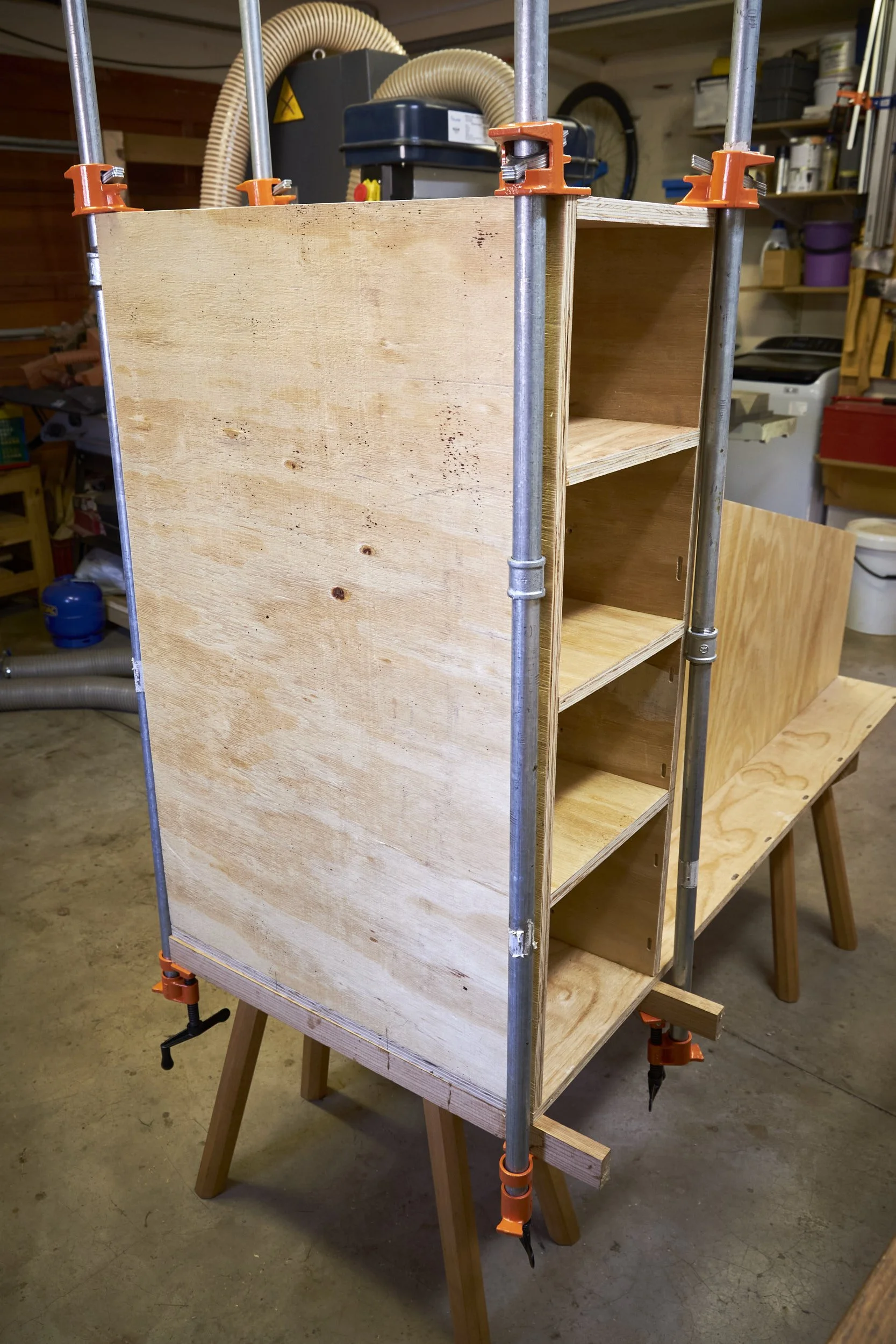
Or “Mid Panel Joinery Using The Festool Domino”? Me and Google SEO are at it again.
How to choose a title that is descriptive and easily searchable? Maybe it’s time to look into AI!
I’m not sure if my research in the area of using the Domino to make mid panel joinery is lacking but there does not seem to be all that much on the subject out there and what there is seems to make some assumptions on aspects of the process that I think may be considered by the presenter as being obvious.
I always say that the best way to learn is to teach and this article takes a relatively deep dive into the process of using the Festool Domino to cut mid panel joinery.
I’ve been looking for an excuse to use the Festool Domino to assemble a cabinet with shelves and said excuse arrived a couple of weeks ago in the form of a new lumber storage cart, this project in turn came about as a result of a confluence of factors that required me to make more space available in the workshop.
It all started with my wife asking me if my Moravian workbench will be spending much more time in the dining room, followed by the fact that I need to accommodate more students in my workshop for training.
So I decided to create more space in the workshop by moving a second workbench into it!
Makes perfect sense doesn’t it?
I needed to start somewhere and after spending an inordinate amount of time drinking coffee and staring into the depths of my humble two car sized workshop while seated on my Nicholson workbench I decided that my old lumber cart was wholly inefficient for storing cutoffs and that it had to be “upgraded”. Also, every time I moved it anywhere in the workshop I had lumber falling out of it and it had become somewhat of an irritation to use.
Some trawling on the net offered up a likeable solution that took up a similar footprint than the original. I settled on this one from Kreg’s website, the design seemed relatively “topple” free and considering that the plans came in at zero cost I had my next project in hand and I now had an excuse to build something and write this article while at it.
With the project plan coming from the Kreg site you would be correct in assuming that the construction method included a few pocket holes. Actually the construction method is a combination of rebates and pocket holes but I decided to do it all with the Domino.
I took delivery of two sheets of 18mm shutter ply, nice cheap stuff, plugged the part dimensions into a cut list optimiser and proceeded to break the stock down with my trusty Metabo KS 55 FS circular saw and track and I soon had a pile of parts that looked nothing like they came out of two full sheets of plywood!
We start the process of assembly by marking out of the joinery, followed by cutting the slots and finish off with a dry fit.
The success of a project like this lies in accurate marking and keeping track of all the parts. It’s for this reason that we will likely spend most of our time here.
Step 1: Marking The Components
I think I counted 20 parts in total for this project which may not sound like much but in my workflow I can almost guarantee that unless I clearly mark each part I will at some point swop something around or get their orientation wrong.
As each part was cut to final dimension I marked it by putting a piece of masking tape on it and writing the part’s name on the tape using a pencil. I then grouped all the parts together in the main assembly that they would become a part of i.e. shelves, base, uprights and vertical compartments.
The orientation of the parts in the project is also rather important or rather shall I say that maintaining the original orientation of parts during construction and final assembly is important if it is to come together square!
I mentioned that the shutter ply I got was relatively cost effective which meant it had one reasonably OK face and another less so on each component. I went through the parts to decide on the orientation of each to show their best faces, if it could be called that at the price point the sheets came in at.
Here are the steps I followed to mark the parts so that I would be able to track their orientation.
Take the sides of the shelf assembly and decide which face will be facing outwards and which short edge will be pointing up.
Now you need to decide which long edge will be facing the front of the completed assembly.
Once you have one face and two edges identified as described above, mark the part so that you will know how to track the orientation going forward.
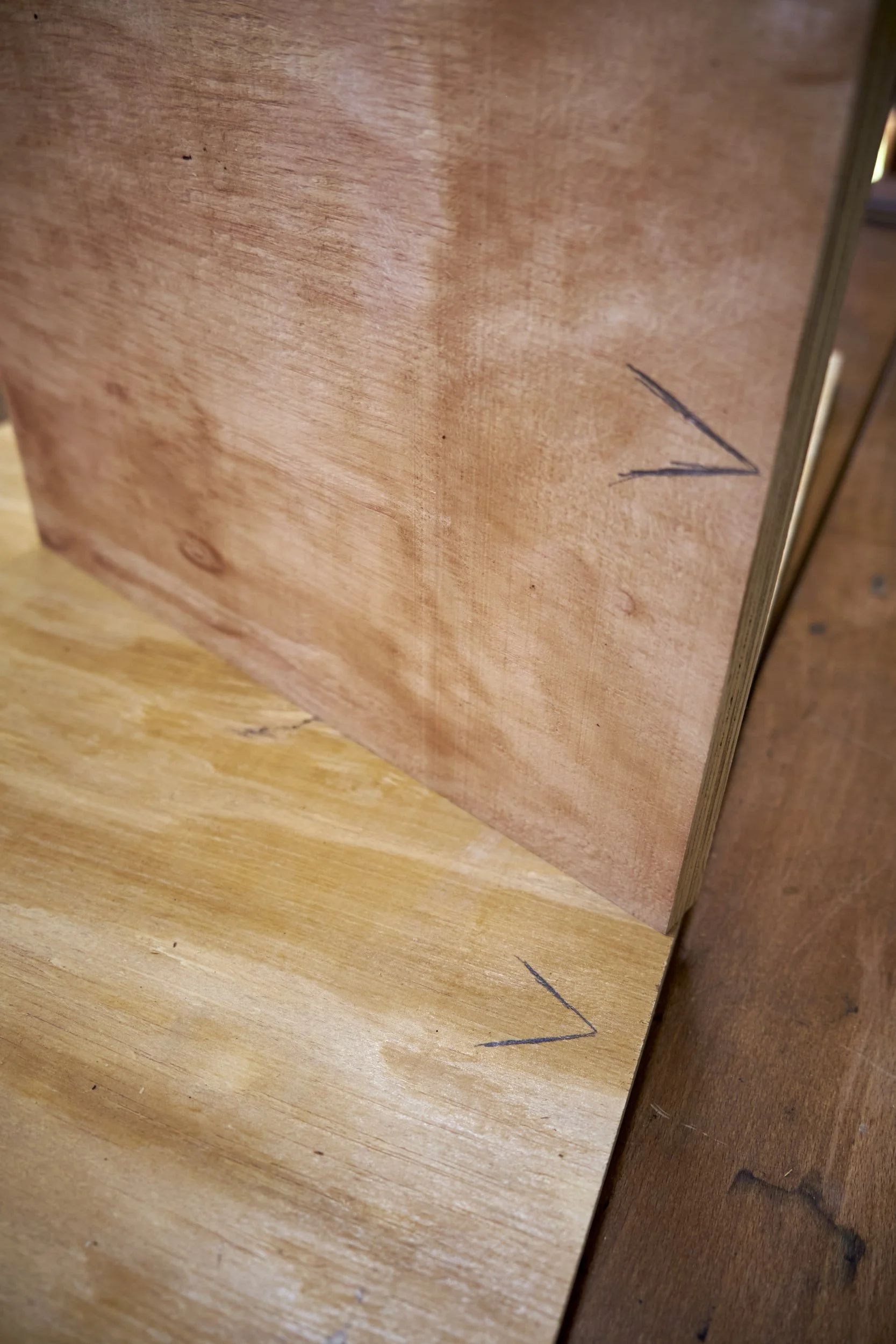
Make a cabinet maker’s triangle or an open arrow on the inside face to indicate the front edge once assembled. I drew this triangle so that one point of the triangle points towards the front edge of the part.
You now know what face will be pointing inwards and which edges will form the top and front of the final assembly.
Do the same with the other side, you may note that if you’ve decided which side will face outward and which way would be up that the front edge is decided for you when you mark the opposing side.
On the shelves you can decide which face will be pointing up and which edge will be the front.
Place a cabinet maker’s triangle on the bottom of each shelf close to the front edge with one point of the triangle orientated towards the front edge.
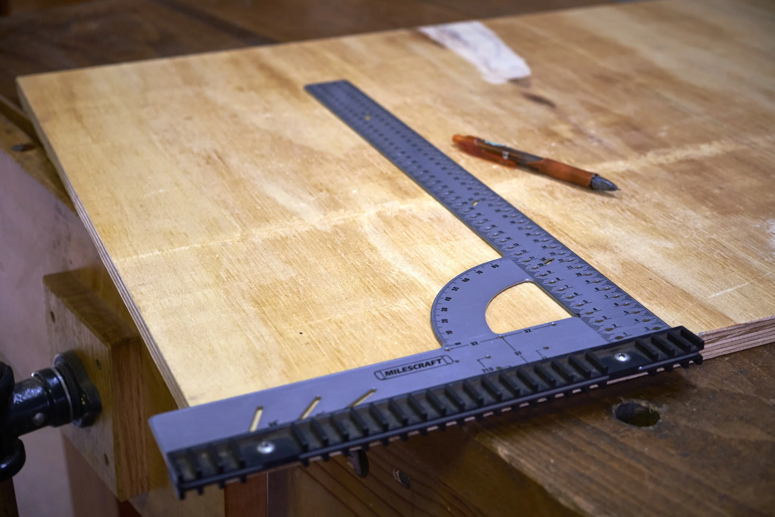
Pro Tip: The dimensions on plans are often suggestions and open to some interpretation especially when measurement of components are taken directly from completed assemblies. Don’t break your head over exact measurements they are only numbers and can more often than not be tweaked to suit any number of factors. The thickness of available raw materials, the final height of a table or a chair, or even not being in the mood to cut parts to weird millimetre sizes just to match exact imperial fractions are only a few of these. Chefs tweak recipes and musicians adapt music all the time to make it their own and there is no shame in changing up a plan and its dimensions every so often to suit your needs.
By the way if you would like to see how I handle inches in my metric workshop you can read more here and if you would like to read more about my method of marking parts you can read more in this post.
Step 2: Laying Out And Marking the Shelf Position
It is at this point in particular that I have found the information about using the Domino for mid panel joinery to be lacking. It also happens to be the area where your project could go horribly wrong if you don’t pay attention. I know that this is the case with all woodworking projects but because the Domino is such a simple solution to use I tend to rush the process and I am prone to making mistakes
The FIRST thing you need to remember is that the lines you are about draw demarcating where the mid panel joinery will be cut will be the reference for positioning the machine and the SECOND thing is that you will NOT be marking the centre lines of the shelves against the sides but rather where the top or bottom surface of the shelf will be after assembly.
Let me explain what I mean and I hope it will become clearer as we move along.
When cutting the joinery the Domino base plate butts up against either the shelf edge or the surface of the side panel depending on which part the loose tenon slot is being cut into. However, as mentioned in the paragraph with the capital letters above these surfaces are not the references from which the joinery is cut but rather they act as “stops” that help guide the machine’s position during the cut. It is the line demarcating where the top or bottom of the shelf will land up during assembly that will be the reference.
I mention top OR bottom surface as YOU will be deciding if you would like to cut the joinery with the shelf either flipping from the bottom up (mark where the bottom edge will land) or the top down (mark where the top edge will land).
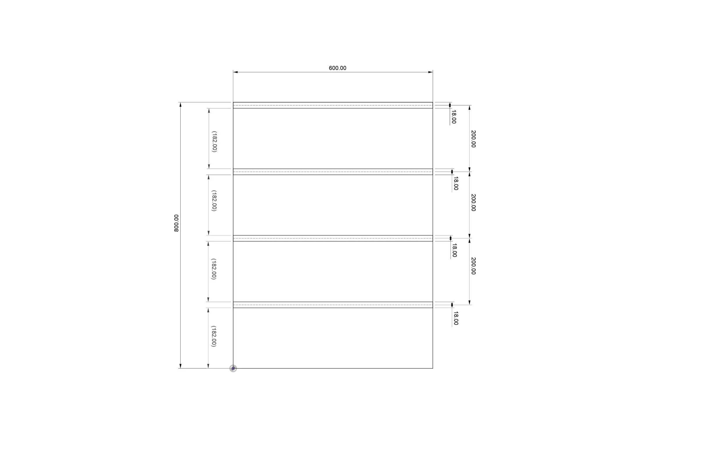
I have spent some time in my design program to draw up a sketch to describe the babbling above in more detail. In the example the large rectangle of 800mm x 600mm represents the inside of the cabinet side panel. The case will have a top that is installed flush with the upper edge of the side panel and the three shelves will be spaced in a manner that will leave an equal amount of space between the bottom surface of a shelf and the top surface of the one below it. The thickness of the stock used is 18mm.
We start with an example showing the ideal spacing we want to end up with:
Joinery marked at the middle of each shelf.
In this example we mark the joinery as we may do in a traditional manner with the construction dotted line showing the mark that we may make to indicate the middle of each shelf. The first mark from the top is made at ½ of the material thickness which will be 9mm. The next shelf position after the first mark is made at 200mm from the top mark and the next again at 200mm below the second and so on. This layout with the stock at 18mm thick leaves us with a 182mm opening between each shelf.
Next we look at the marking that we would implement if we decided that we wanted to flip the shelf from the top down and thus marked the final position of the top edge of each shelf:
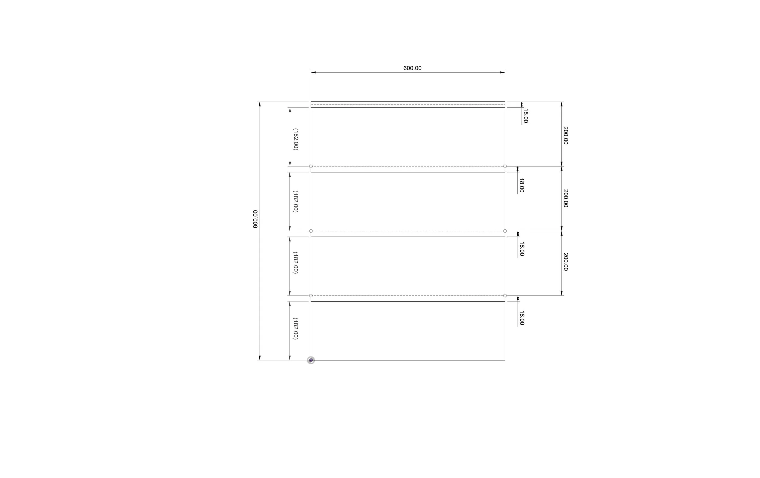
Position marked to indicate the top of each shelf.
The global dimensions remain the same as with the prior example but now the layout lines demarcate the final position of the top edge of each shelf. The dotted line now shows both the top edge of the shelf and the layout line (I actually deleted the line for the shelf as it obstructs the layout line). Here we start with a line measured 200mm from the top of the side panel and the next 200mm from the first and the last layout line 200mm from the second.
Lastly we look at what will happen if we get it wrong:
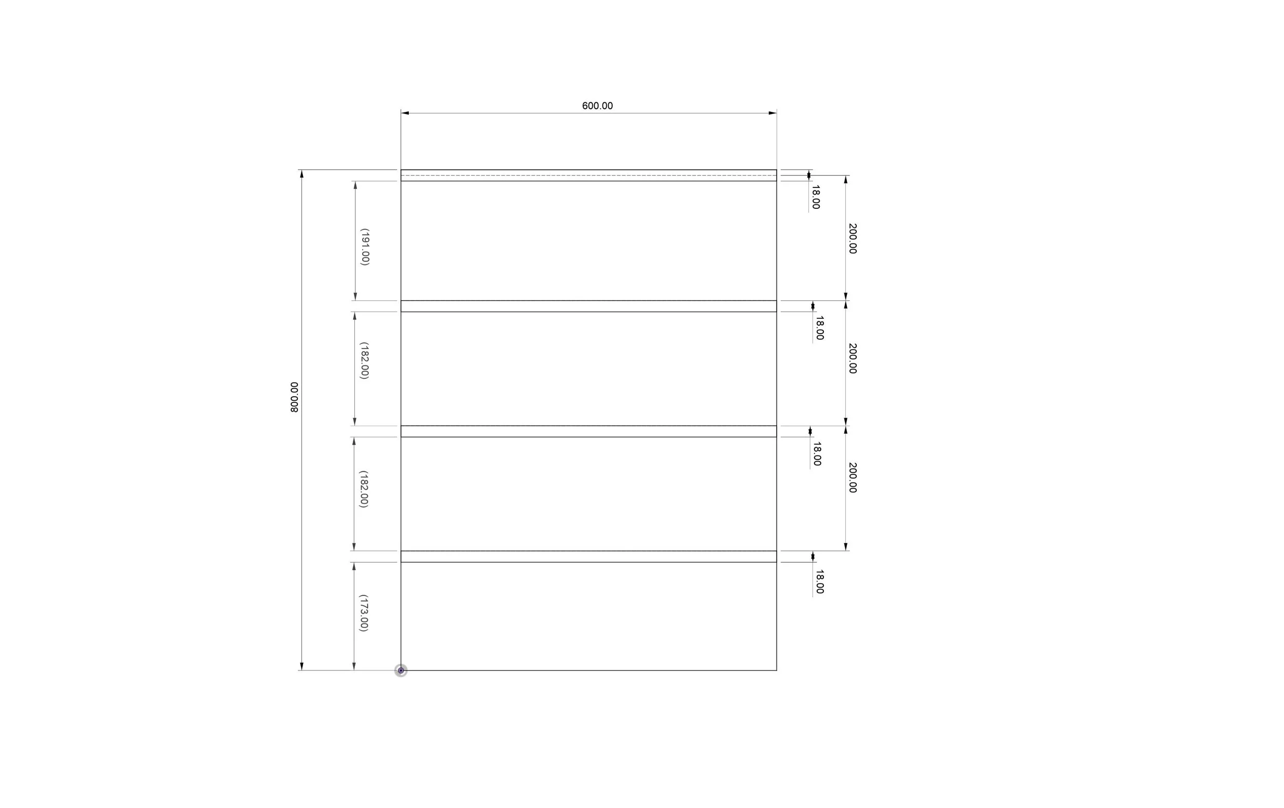
What happens if the shelves are aligned to the middle mark?
In this example we mark the layout at the middle of each shelf as we did in the first example but then register the top of each shelf against the layout line, as we would position the shelf when cutting the slots. You may note that it screws up the spacing between each shelf.
Phew, that was a mouthful and we haven’t even started on the step by step yet!
So, here we go!
Start with a single side panel on the workbench with what will be the inside surface pointing up.
Now lay out what will be either the top or bottom edge of each shelf. This will depend on your choice, flip up or down, considering the desired spacing between shelves of your own project.
Using the example above to mark the top edge of each shelf, make a mark at 200mm from the top and then a mark at every 200mm from the previous until you run out of shelves or space whichever comes first! In this example, three marks.
Carry the marks that you’ve made across the full width of the side using a square.
Now bring the second side panel and line it up next to the first so that the top and bottom edges are flush with one another. The sides should also butt up against one another and you need to make sure that the marks that indicate what will be the front of the cabinet also orientate correctly. Do this by either having the front edges against one another or the back edges facing one another.
Transfer the marks that you have made on the first panel over to the second and strike these across the second panel, again using a square.
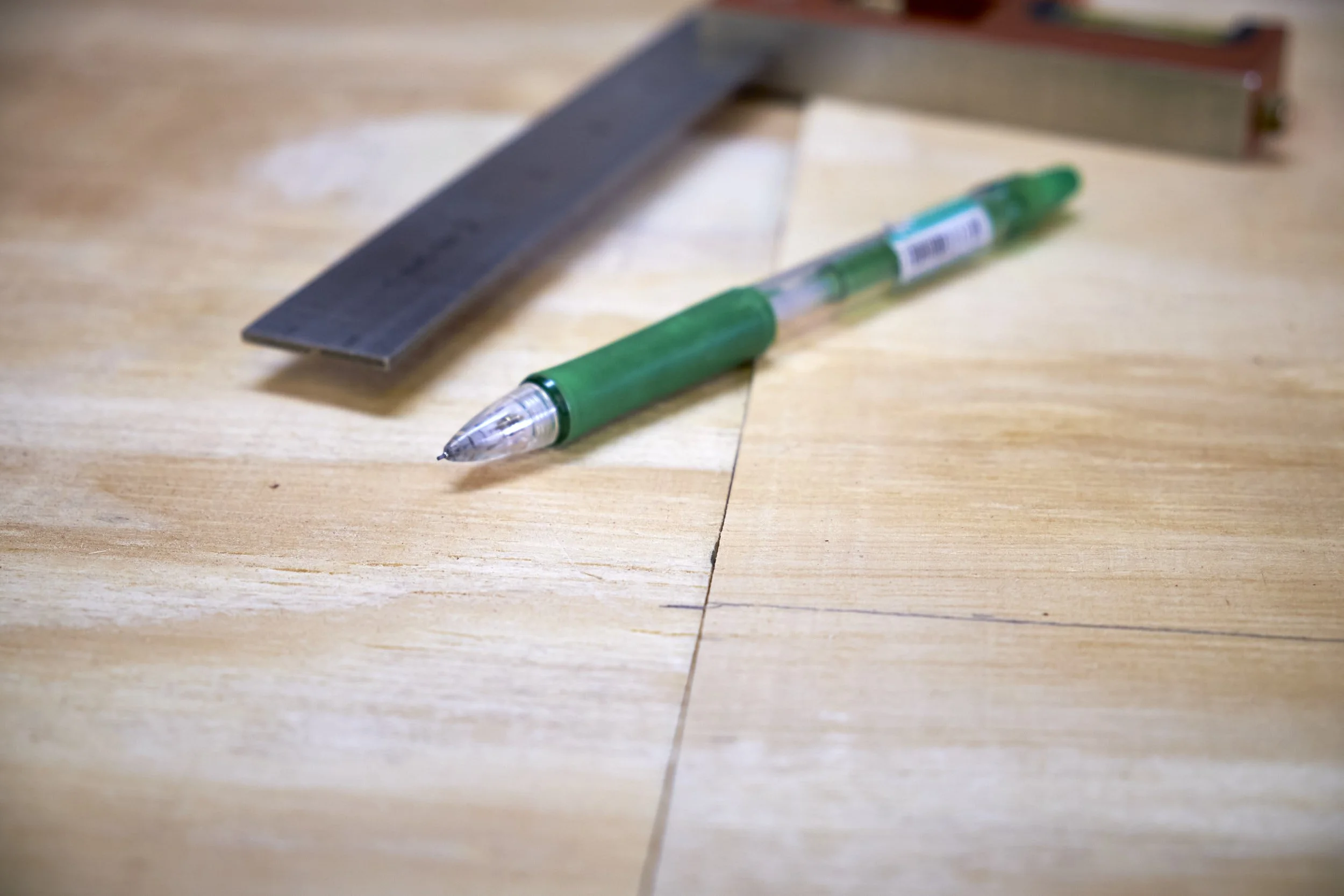
Ok, reference lines demarcating what will either be the top or bottom surface of the shelves made across both side panels. The reason for marking the second from the first is to help ensure that the shelves sit square between the sides.
Pro Tip: I may have harped on about this one before, but it is always a good idea to mark one workpiece from the completed layout on another if the two parts will mirror one another. This will ensure that parts line up and if you did happen to make a measuring mistake on the first you will carry this over to the second and the parts will still likely line up and hardly anyone will notice the mistake. Just don’t mark the leg position of a table in the middle of an apron, someone may notice that one!
As with all things woodworking there are a myriad of ways to lay out the positions of the shelves and as I am writing this I can think of at least one more and although the method in my head may be simpler it will take longer so I won’t elaborate on it here. You may have a preferred method and if you believe it is simpler please tell us in the comments below, I always like to learn new ways of doing things, especially those that are so obvious that you end up asking why you didn’t think of it in the first place.
By the way marking the shelf position in this manner is nothing new and I often mark only the top or bottom edge of the shelf when I use dados to construct a cabinet. I do sometimes forget on which side of the line the dados should be cut but that is a story for another time.
The marking out is not done yet though, and next we look at where to cut the slots for the loose tenons.
Step 3: Marking The Tenon Positions
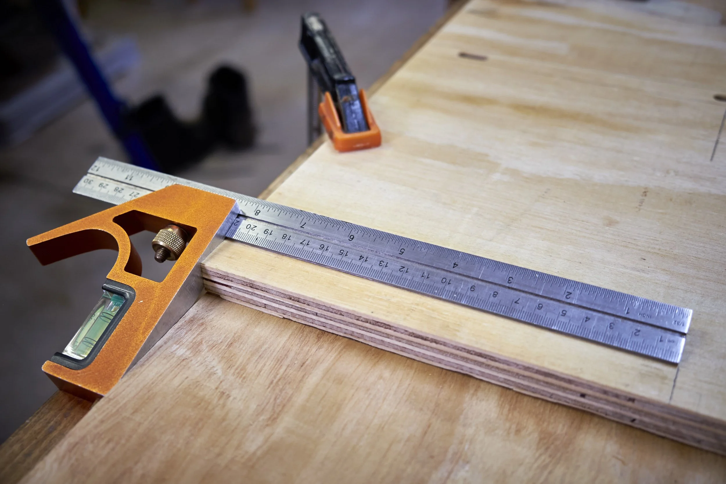
The good news is that this process isn’t as hard to explain as step 2 and the design of the Festool Domino makes this easy because we will be using the stop latches to cut the slots closest to the edges of the parts, meaning that for half of the slots for the loose tenons no measurement or marking would be required.
In prepping for this how to I used 3 different methods to do the this layout and I was going to detail each in this section but I decided to spare you and only focus on the easiest one! I did have an epiphany whilst using this method that led to the realisation that ONLY the shelves needed to be marked to indicate the position of each loose tenon on both the shelf and the side panel.
You will see how it works in a bit.
On to marking, again using our example to work from.
At 600mm wide I decided to put 4 loose tenons into each joint.
To mark the pair in the middle divide the width of the panel into 3 and you will get 200mm.
Position the shelf so the same surface that will be pointing up during the cutting process is pointing up on your bench. This depends on the direction of the flip you have decided on. Top surface if flipping up and bottom surface if flipping down.
Set a combination square so that 210mm of the blade protrudes from the square’s reference stock and register this against either edge of the shelf. I used 210mm rather than the calculated 200mm.
Make a mark at the tip of the square’s blade or in other words at 210mm.
Repeat from the other edge.
The slots at either edge of the sides and shelves are taken care of by the stop latches on the machine, provided that the shelves are as long as the sides are wide.
Now things get fun, using the Domino is always fun!
Step 4: Set Up For The Cut
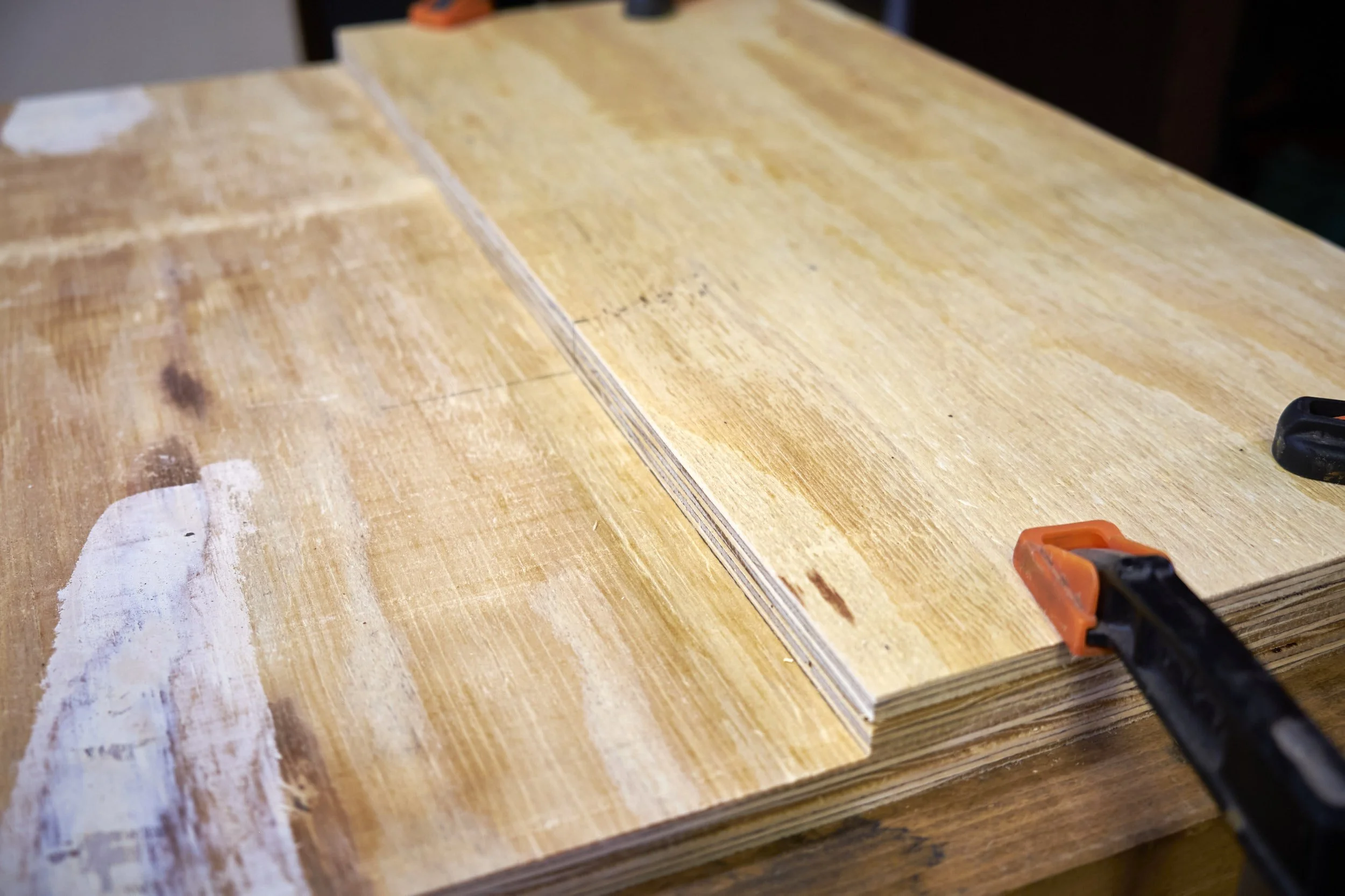
Ok you now have side panels and shelves marked and ready for the joinery and assembly process.
I am hoping that this will be easier to explain than steps 1-3 but before we continue I need to mention that I chose 8 x 40mm Dominos to put it all together. Keep in mind that at 18mm thick you will cut through your stock when cutting the slots into the sides.
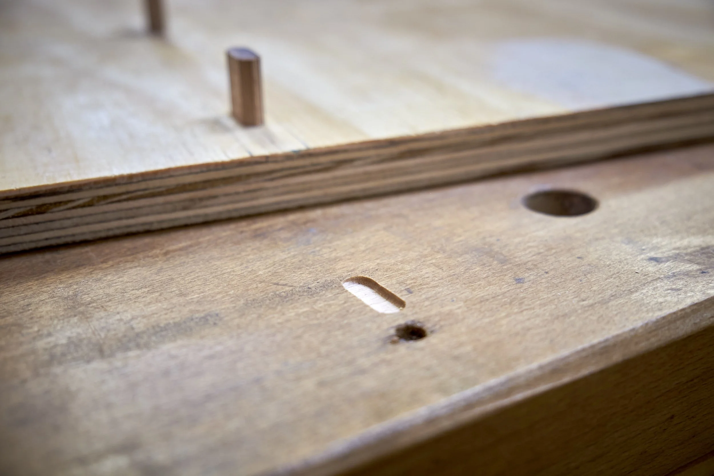
Look what I did to my workbench on the first cut!! Not to worry the slot will be gone in about 2 years as I flatten my workbench.
Set the depth of the machine to cut 25mm into the edge of the shelves and 15mm into the side panels, the total depth will accommodate the 40mm loose tenons.
Here we go:
Place the first side panel that you will be working on, onto a flat work surface with the side that the shelves be attached to, facing up.
Line up the top or bottom edge of the first shelf that will be installed with the mark that you made across the side panel to show where the top or bottom edge of the shelf will fall. In other words if you’ve marked the top edge on the side, line the top edge (flip down) of the shelf up with the mark and vice versa if you’ve marked the bottom edge (flip up).
If you have done everything correctly the bottom or top surface of the shelf will be laying against the surface of the side panel and the top or bottom edge will line up with the mark made earlier along the width of the side panel. The marks indicating where the loose tenon slots will be cut should be facing up towards you.
Also make sure that the front and back edges of the shelf is flush with both the front and back edges of the side panel.
Secure the shelf and side panel to the work surface so that they will not move while using the Domino machine.
On to cutting the slots.
Step 5: Cut Mortises Into The Side Panel
Make sure you have the correct cutter in the machine, in my case 8mm.
For the sake of the exercise we start with the slots on the side panel.
Set the correct depth on the machine for the cut you will make, 15mm for the side panels.
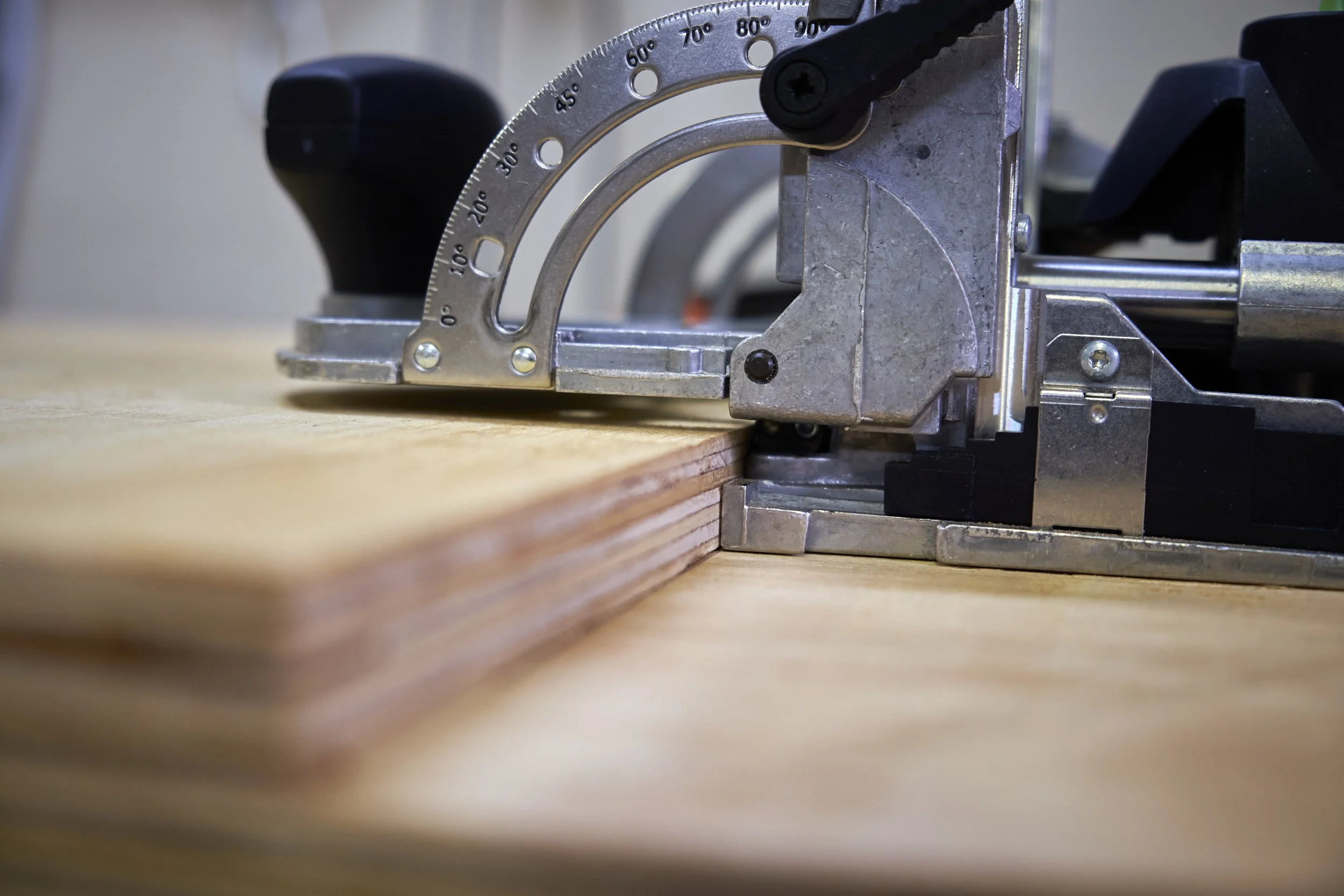
Flip the angle fence up to 0º and lock in place.
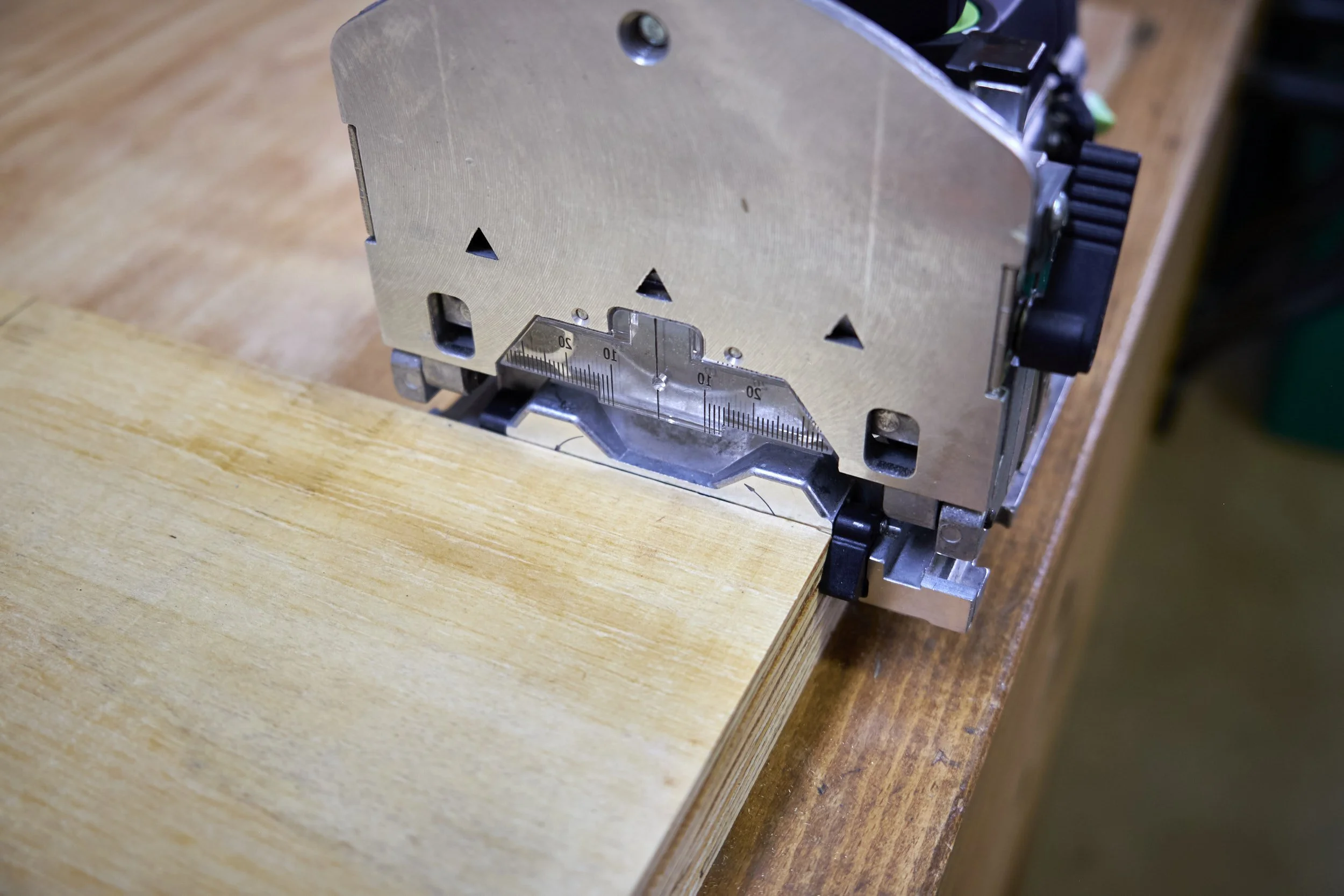
Position the machine so that the angle fence is flush with the side panel surface and the baseplate registers agains the edge of the shelf.
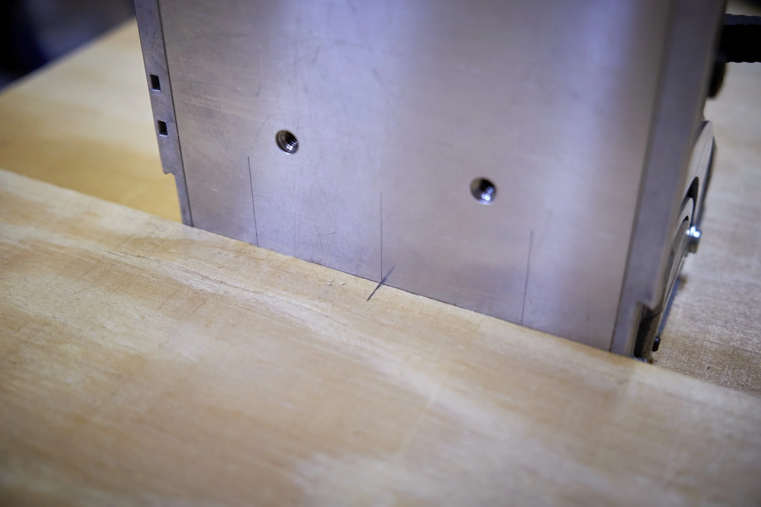
Line the centre mark inscribed on the base plate up with one of the mortise position marks on the shelf.
Keep the machine steady and lined up as described above and make the cut.
Move on to the next marked position and cut the mortise.
On the front and back edges of the side panel do the following.
Position the machine as described above.
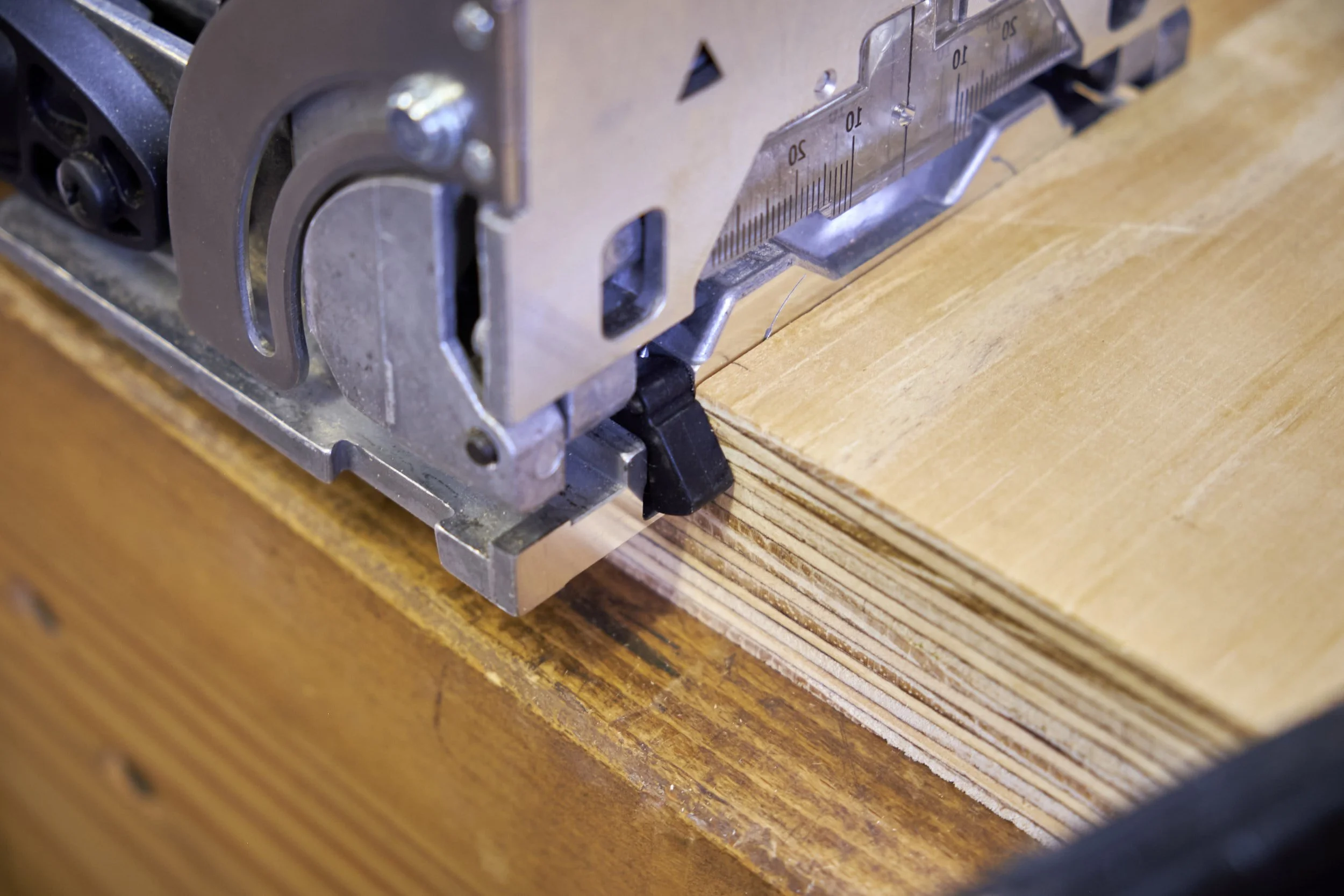
Move the machine over the front or back edge until stop latch pops down past the edge of the side panel.
Move the machine towards the middle of the side panel so that the latch registers against the front or back edge of the side panel.
Keep the machine steady and cut the slot.
Cut all the slots in the side panel for the shelf being installed before moving on to the next step.
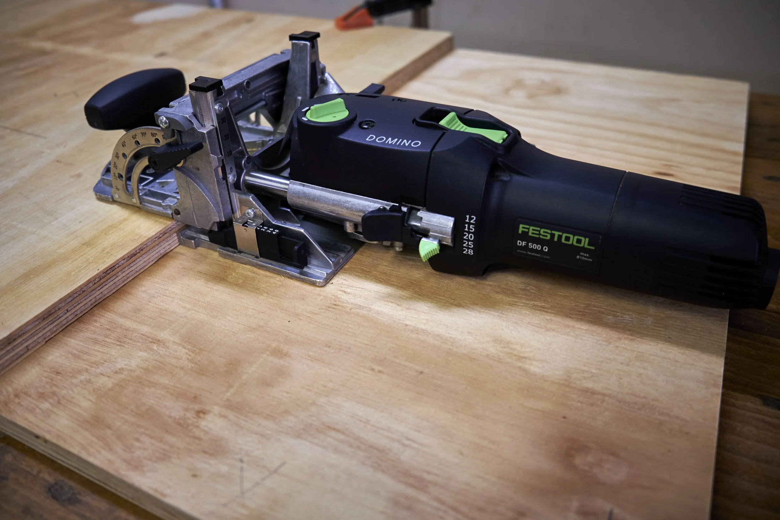
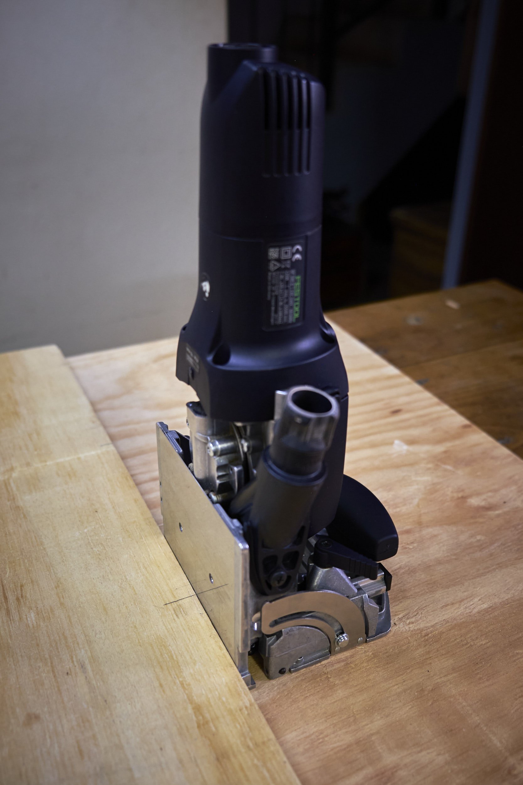
Step 6: Cut Mortises Into The Shelf
With the mortises in the side panel done we go on to the shelf.
Set the depth of cut to 25mm.
Flip the angle fence to 90º and secure.
Use the board thickness gauge and set the angle fence height to 20mm.
Place the machine so that the base plate sits flat on the surface of the side panel and push the front edge of the base plate up against the edge of the shelf.
Align the centre mark of the horizontal position gauge with the mark you made indicating the position of the mortise on the shelf.
Make the cut.
For the front and back edge of the shelf use the same method detailed above using the stop latch on either side of the machine.
You may notice that if you follow the steps detailed above for setting the angle fence height to 20mm that the fence will be slightly above the surface of the shelf, leaving a slight gap between the fence and the surface of the shelf. This does not matter as the height of the cut in the shelf edge is determined by the distance from the base plate to the middle of the cutter and not the height setting of the fence.
Once all the slots have been cut install the loose tenons and do a test fit of the shelf to the side panel. The top or the bottom edge of the shelf should line up with the mark made across the side panel to show the shelf’s position and the front and back edge of the shelf should line up with the front and back edge of the side panel.
Also check if the shelf is square to the face of the side panel.
Step 7: Cut The Rest
Almost done.
Cut the joinery for the rest of the shelves in turn moving towards the top or bottom shelf depending where you started and dry fit each.
Move over to the opposing side panel and repeat whilst making sure that the shelf and side panel orientation is correct according to the marking made in steps 1-3.
Dry fit all parts and make sure it all goes together square before gluing up the assembly.
Don’t forget to cut the joinery for the top shelf as per normal.
Pro Tip: Rather than fiddle with the machine settings by returning to the side panel mortise setup after completing a shelf, keep the settings as is and first cut the shelf joinery of the next shelf as detailed in step 6 before moving back to the side panel mortise setup as detailed in step 5. Again keep the side panel settings for the next position before changing up for that position’s shelf. This will save a bit of time and is almost like leapfrogging setups.
If you are still with me, I am impressed!
Why does this method work for cutting mid panel joinery? I did mention earlier that the lines that mark the position of the top or bottom edge of the shelf are the real reference that you work from and it’s these together with the bottom of the base plate that make the magic happen.
The distance from the base plate bottom to the middle of the cut is always 10mm irrespective of the size of the cutter used thus the middle of the mortice is always 10mm up/down from the surface the base plate is registered against. When cutting slots into components as detailed above the middle of the mortise in the edge of the shelf is 10mm up from the side panel surface and the slot in the side panel is 10mm away from the mark made to show the shelf position, the shelf is merely positioned to act as a fence for the base plate to reference from.
The reason the position of the top or bottom edge of the shelf is important is because not all laminates are 20mm thick, so using the base plate to fix the distance of the slot from it’s respective reference face won’t place the middle of the slot in the middle of the edge of a board and thus not in the middle of the joinery that brings the shelf and side together.
This method allows you to cut the joinery easily using the constant 10mm base plate to centre of cut dimension, irrespective of the thickness of the material used. This does mean that the slots will be offset from centre but if you keep your choice of tenon size and remaining stock above and below the mortise reasonable you will be good.
I’m hoping the sketch below will help. It shows the side panel (bottom) and the shelf (top) with the positions of the slots shown within each. You will note the mortises are offset as a result of referencing from the base plate but because we are cutting the mortises from the same reference point (line demarcating the top edge of the shelf), the mortises will align perfectly when we flip the shelf upright.
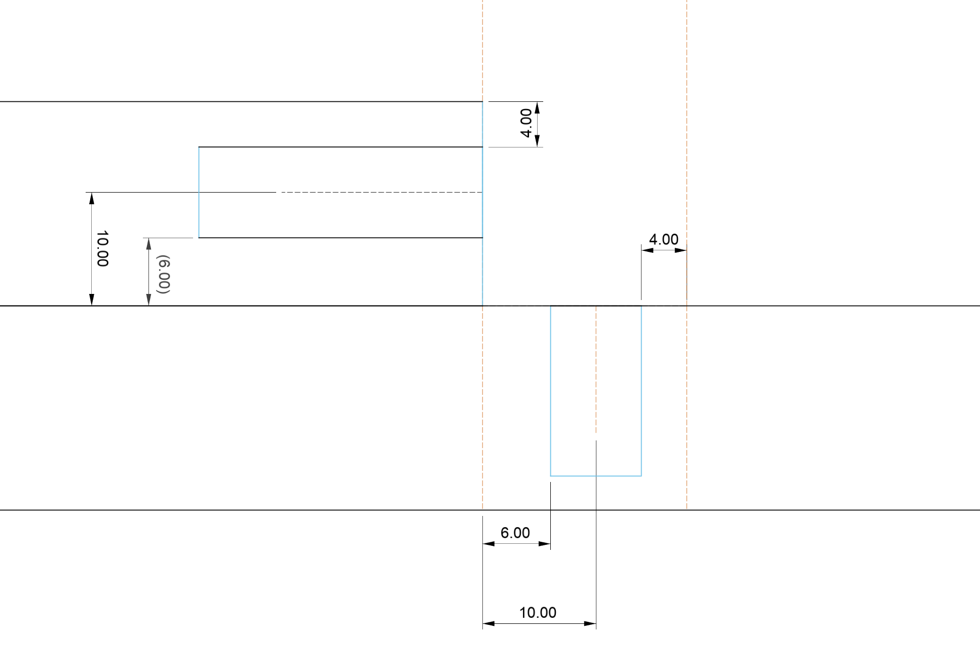
Mortise position after cut.
I’m hoping this sketch will help. It shows the side panel (bottom) and the shelf (top) with the positions of the slots shown within each. You will note the mortises are offset as a result of referencing from the base plate but because we are cutting the mortises from the same reference point (line demarcating the top edge of the shelf), the mortises will align perfectly when we flip the shelf upright.
See it all makes perfect sense………
That brings us to the end of “Mid Panel Joinery Using The Festool Domino”.
Until next time, go build something cool, if you haven’t yet try using the Festool Domino to make something with mid panel joinery and see for yourself how easy it is!
As a bit of news on the side I’m working on another plan set, this one is for a little push block that will help you work more safely on your table saw, I might even include it on the free plan page so if you would like to have access to my FREE plans and get first dibs on special offers and news, sign up here.
The Festool DF 500 connector system, five small parts with massive potential. Over the past few months I have built six pieces of knock down furniture on client commissions and the system has opened a whole new thinking about the results that it can help me achieve.