
Essential Tips for Keeping Your Jointer Aligned
This is going to be a two parter with the first focussing on general alignments on the machine and part two covering the blade installation, set up and final checks.
The jointer, of all the machines that I have invested in since taking up woodworking full time would likely rank as one of THE game changers in my workflow. Before I made the investment I jointed boards using hand planes and the machine saves a lot of time.
Once or twice a year all my floor standing equipment gets a once over during which they are cleaned, vacuumed, blown out, lubricated and aligned. The jointer is no different but I like to take special care on the jointer during maintenance as it form the basis for all my lumber processing at the start and during projects.
The first step in the maintenance process is to sharpen the blades and in my last article I went through the process of how I get sharp blades using the Veritas Jointer Blade Sharpener and the scary sharp system. You can read more on the process and what I think about this jig from Veritas here.
Part one details my process to check and correct the alignments on the machine and in part two of the series I re-install the blades and complete the final checks.
Note - Make sure that any machine is disconnected from the mains before you do any work on it, also be sure to read the manual and fully familiarise yourself with its components and safe operation.
Before I start, I find it useful to remove the safety guard and fence as this provides easy access to all the parts I’ll be working on.
Step 1: Check Coplanar
While confirming the definition of “coplanar” I just learnt that I’ve have been spelling it wrong!
At least the definition I had in my head matches the literature.
A jointer has four major parts apart from the motor, those are the in-feed and out-feed tables, the cutter head and the fence. When I talk about being coplanar on the jointer I generally refer to the in-feed and out-feed tables. It is important for the accuracy of the machine that these two tables are coplanar to one another in two different axes.
The first axis to pay attention to is along the length of the two tables from left to right and in short means that the far ends of each table should be level with one another along the full length of the machine, with no dips or rises in the middle or anywhere between these two points.
The second axis is diagonally across the tables between their opposing corners. This is to check that the tables are on the same plane across their width and not “twisted” in relation to one another.
Disclaimer, my jointer has never needed adjustments to correct the alignment between the tables but I do check it as explained below.
How to check:
Raise both the in-feed and out-feed tables so that their surfaces are above the cutter head.
Place a straight edge across the gap, I use the blade of one of my engineering squares.
Lower or raise the tables so that they are perfectly level with one another, using the square to check alignment.
Place a long, accurate straight edge along the front edge of both tables.
While holding the straight edge firmly down on one table (typically the out-feed) use feeler gauges to check if there are any gaps between the straight edge and either table.
Take note of the size of the gaps and where they are.
Now move the straight edge to the far edge of the tables and repeat.
If there are no or negligible gaps you are good to go on to the next step. Check the notes below on what one might consider as negligible.
What happens if it’s wrong:
If there is an issue on the first axis along the length of the tables you run the risk of forming a bow or a cup in the boards you are processing.
If the problem is on the diagonal axis you may plane a twist into the lumber.
How to fix it:
As mentioned, I have never personally needed to make any corrections to the tables so I’m going to send you to the following links for help if the tables on your jointer need any adjustments.
I like the following videos:
Notes:
You are not going for engineering accurate here and I generally start fixing when discrepancies exceed 0.5mm or around 0.020”.
Try to use an accurate straight edge as close as you can to the full combined length of the in-feed and out-feed tables. If you do not have access to such a long edge use one that is at least long enough to breach the gap between the two tables with one end set at the end of the table. This way you can use the previously checked section as the reference for the next.
Step 2: Check Cutter Head
I’ve only recently started paying attention to the alignment of the cutter head to the tables and this has simplified the blade installation somewhat.
I differ with some opinions out there on this one but I consider the out-feed table as my reference for all further adjustments once the tables are confirmed as coplanar. As a result all alignments going forward will be made in relation to the out-feed.
How to check:
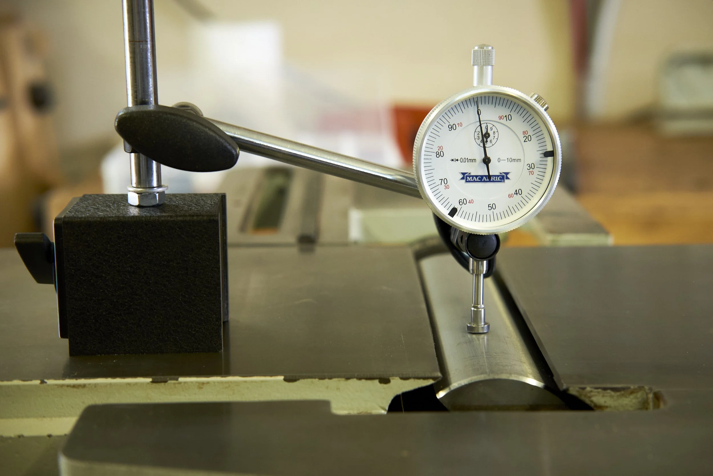
I use a dial indicator with a magnetic base to check this setting.
Rotate the cutter head so as to allow access to an area between two blade positions.
Ideally it is best to move the head with the blades removed to avoid slicing any appendages. On my jointer I have access to the drive belts at the back of the machine and I can turn the pulley to move the head rather than having to get my fingers in there to do so.
Position the dial indicator over the cutter head and set it up so that the dial indicator’s contact point just touches the head’s surface at the apex of its rotation. The picture gives you an idea of what you are looking for.
Set the dial indicator to zero using whatever method your instrument requires.
Move the indicator along the length of the head paying close attention to the measurements on the indicator, take note of which side is lower or higher than the other and jot down the measurement somewhere.
Keep even pressure on the base while moving the assembly along the width of the out-feed table, this will ensure that the indicator does not dip down and affect the readings.
What happens if it’s wrong:
If the blades are aligned to the surface of the cutter head and the head itself is not parallel to the out-feed table the blades will not cut the lumber parallel to the out-feed table’s surface.
This will result in a cut that will taper the bottom of the plank being jointed, either from the left to the right of the plank across its width or vice versa depending on which side of the head is lower than the other.
A slight taper as a result of non parallel blades isn’t critical and it will be corrected during thicknessing anyway. Of course a large taper will affect accuracy and waste raw material.
What will keep you busy if the blades are not parallel to the out-feed is that you will have a hard time getting the edges of the lumber square to the jointed face, even if your fence is perfectly square to the out-feed your blades will be cutting at a slight angle resulting en an edge that isn’t 90º to the face.
How to fix it:
You will be fixing the low end of the cutter head by putting a spacer in under the cutter head bracket that holds it down in the jointer chassis.
Wortheffort’s video here again explains this procedure in detail.
Using the measurement taken on the dial indicator find the feeler gauge at the exact value or at least the closest to the number jotted down during the checking step. You may need to combine more than one gauge to get to the target value.
On the side to be lifted, loosen the nut on the retaining bolt holding the cutting head down and slip the feeler gauge under the bracket that holds the cutter head in place.
Tighten the nut to re-tension the bracket onto the feeler gauge.
Re-check the alignment using the dial indicator. If the needle stays at zero or close to, you are done if not, try thicker or thinner shims until you get the alignment to optimal.
Pro Tip: Have a basic set of feeler gauges available in the workshop that can be cannibalised to shim components. It takes the need to experiment with pieces of soda can or whatever else is on hand to get the correct spacing and simplifies the process significantly. Feeler gauges also do not deform in use over time so they are the best option for one time fixes. Feeler gauges are cheap and make perfect shims.
Keep in mind that variations in manufacturing can result in slight changes in the diameter of the cutter head and that these will show up on the dial indicator as it’s moved along the head’s surface. Do not worry about slight discrepancies along the length, you are looking for obvious shifts between one side of the head and the other. I will typically attempt to correct errors of around 0.5mm or 0.020” and up.
Note - After conducting any work on any machine make sure that all nuts, bolts or anything that was removed or loosened is re-tightened or installed back where it belongs before starting up the machine. The same goes for removing tools or any unsecured components that can get into moving parts when the machine is switched on.
Next one is a deep dive into installing the blades and the steps to set them up and final checks.
As alway if you would like to be kept in the loop of when new posts drop or if you would like access to my FREE plans, please consider signing up for my newsletter here.
Feel free to let me know in the comments if you find this kind of material useful and if not tell me why and I will try to improve.
Low angle jack planes are often sold as the ultimate do-it-all hand plane, but they may not be the best first choice for beginners. Here’s why I would usually start with a standard No. 5 jack plane instead.